

Project Overview
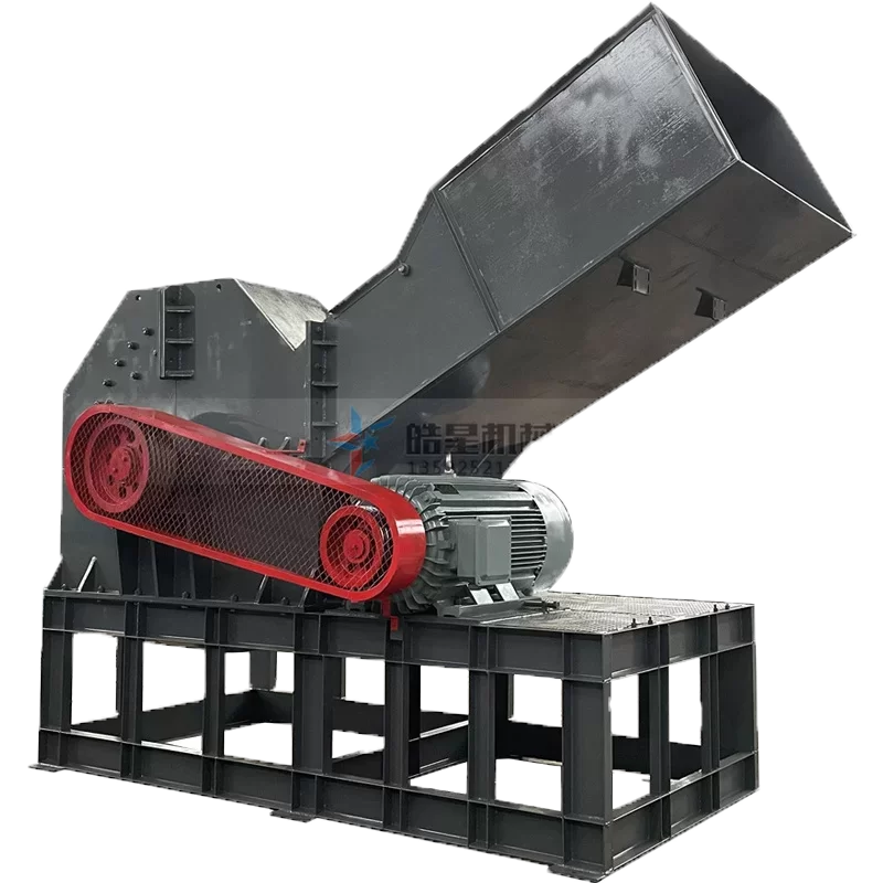
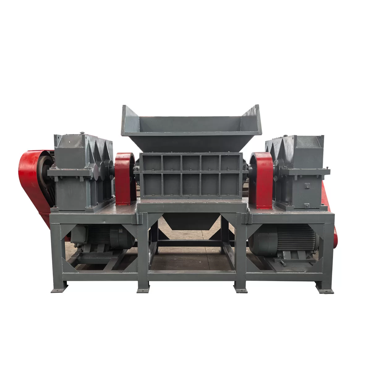
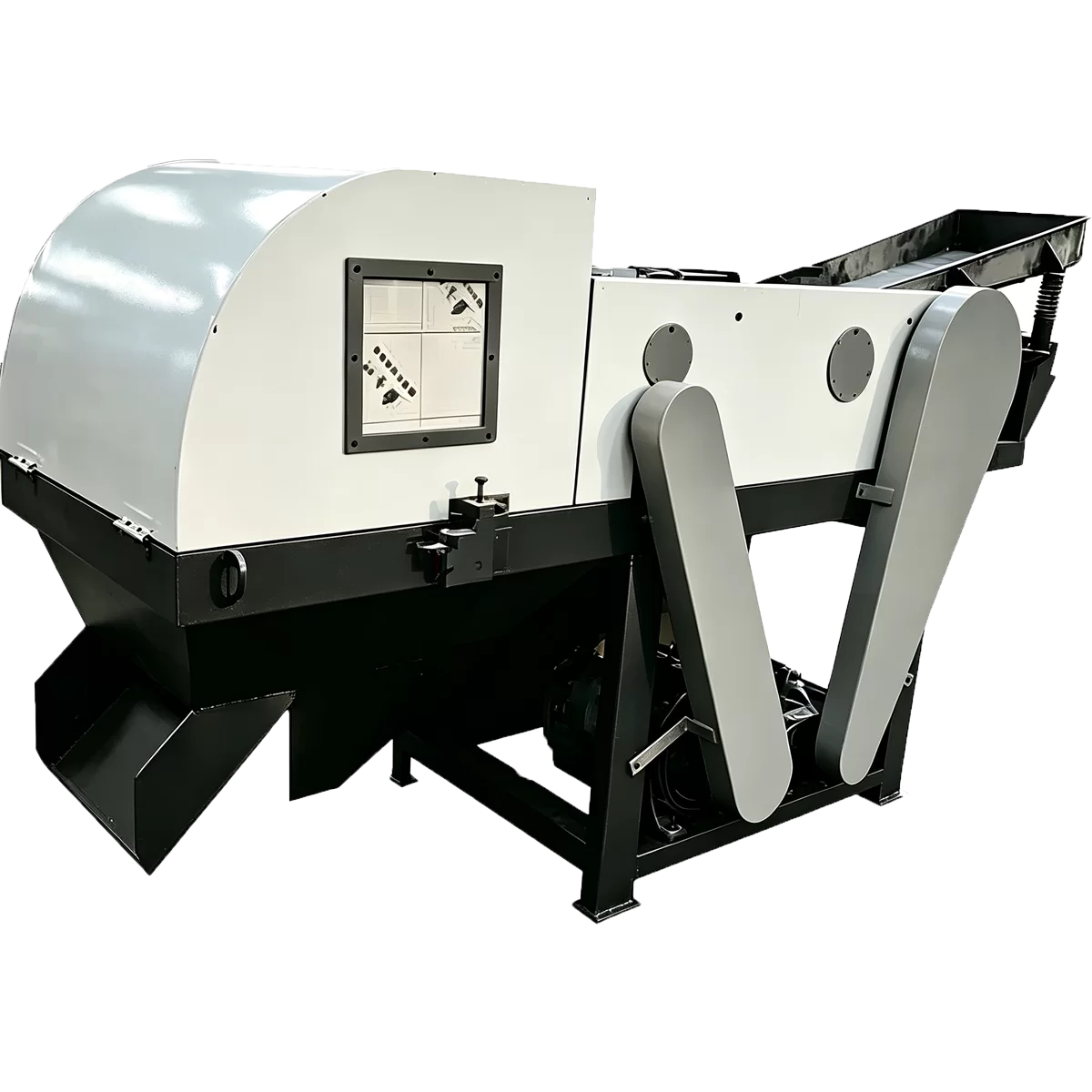
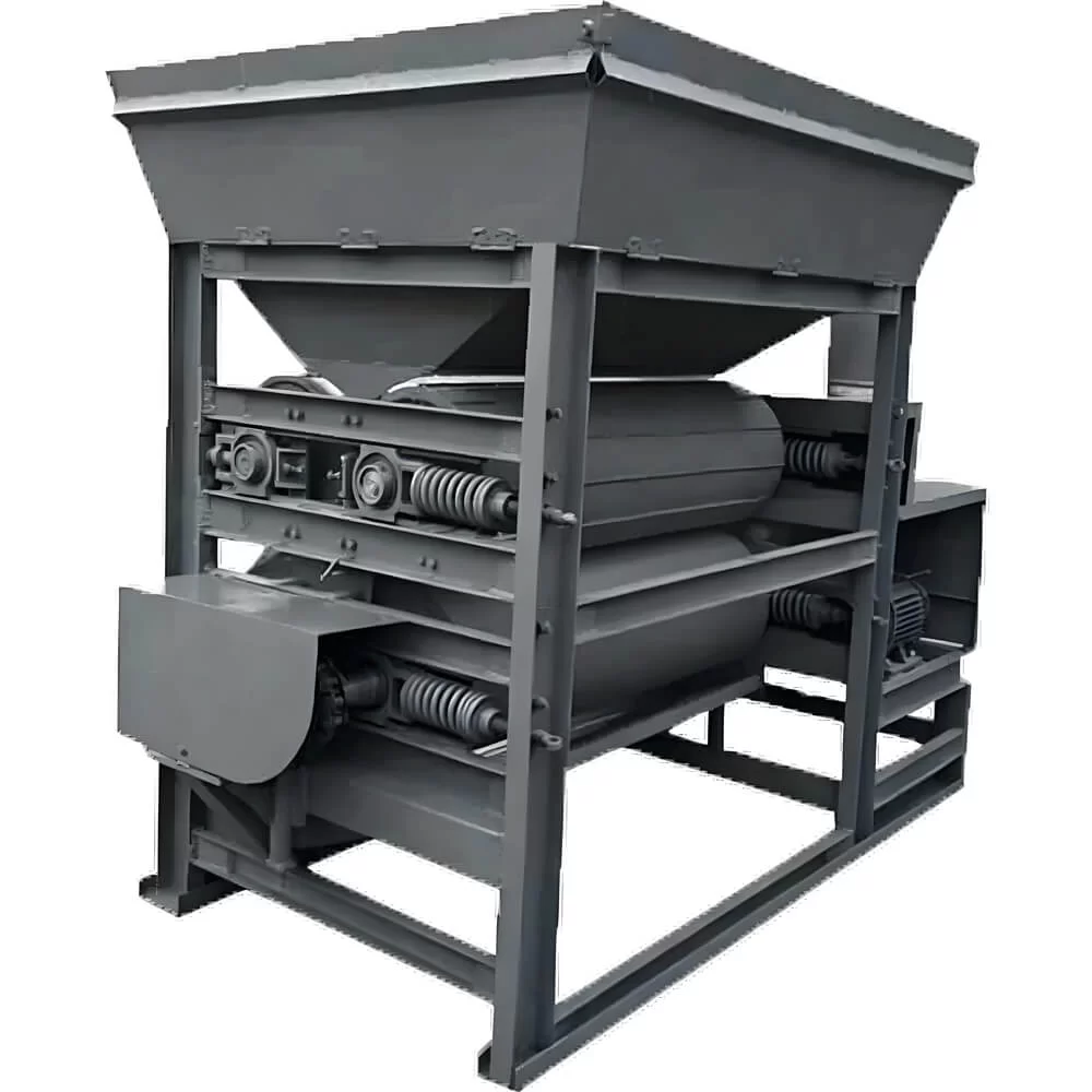
Factory real shots of twin shaft shredder gearbox showing the transmission structure, installation details, and assembly scene. Suitable for a manufacturer showcase page and helpful for buyers checking core component configuration.

Introduction
These photos show the real factory installation and structural details of the twin shaft shredder gearbox. As one of the core transmission parts of a twin shaft shredder, the gearbox has a direct influence on torque output, running stability, and long-term working performance. A real shot case gives visitors a clearer view of the machine structure, assembly quality, and workshop condition.
Main Content
A twin shaft shredder is widely used for processing metal, plastic, rubber, wood, and household waste materials. During actual operation, the machine must handle heavy impact loads, so gearbox selection and installation are especially important. Based on different materials and capacity requirements, the manufacturer will match suitable gearbox specifications to keep the whole machine running more smoothly.
From the factory photos, it can be seen that the twin shaft shredder gearbox is closely integrated with the main shaft drive system. The structure is compact, the installation position is clear, and later maintenance becomes easier. The main function of the gearbox is not only to reduce speed, but also to increase torque output, allowing the cutter shafts to maintain strong shredding power when processing bulky materials.
In real production, the stability of the gearbox directly affects the working performance of the whole shredder. If the transmission system is not properly matched, the machine may suffer from load fluctuation, unstable operation, or faster wear. That is why manufacturers usually pay close attention to the coupling, bearing housing, transmission clearance, and installation level during assembly.
These factory real shots also reflect the manufacturing standards of the equipment. Whether it is the frame structure, transmission part, or gearbox installation method, the machine is built according to actual production requirements rather than simple assembly. For buyers, this kind of content is more practical and helps evaluate whether the equipment is suitable for their working conditions.
When checking a twin shaft shredder gearbox configuration, it is recommended to pay attention to material hardness, feeding size, capacity requirement, and future maintenance conditions. Only when these factors are properly matched can the machine run more stably and keep operating costs under better control.
Conclusion
The above is a factory real shot case of a twin shaft shredder gearbox. HXO Machinery can provide suitable twin shaft shredder solutions according to different materials and output requirements, helping customers choose the right transmission system and shredding structure.
Gearbox Selection Must Follow Shaft Torque
A twin shaft shredder gearbox should be selected from required cutter-shaft torque, operating speed, shock load, service factor and expected reversing frequency. Motor power alone does not define the correct gearbox. The reduction ratio, rated output torque, allowable peak load, thermal capacity and coupling arrangement must be checked together.
Two Independent Drives or a Synchronized Arrangement
Depending on machine size and process requirements, the cutter shafts may use separate motor and gearbox assemblies or another engineered synchronization arrangement. Independent drives can support shaft-specific load control, while the control program must still coordinate direction, speed, overload response and automatic reversing. The selected structure should match the cutter layout and material behavior.
Cutter Shaft and Gearbox Are One Load System
Shaft diameter, working length, cutter width, hook profile, spacer arrangement, bearing span and material strength affect the load transferred to the gearbox. A longer chamber or more aggressive cutter does not automatically increase useful capacity. It can also increase torque demand, bending load and the risk of repeated overload if the feed is too dense.
Couplings, Bearings and Alignment
Gearboxes, couplings, bearing housings and cutter shafts must be installed on a rigid, accurately machined base. Misalignment can increase vibration, seal wear, bearing temperature and tooth loading. The maintenance plan should include fastener checks, lubricant inspection, temperature monitoring, coupling condition and abnormal-noise review.
Automatic Reversing Is Protection, Not Unlimited Capacity
Automatic reversing can release temporary jams and redistribute material, but frequent reversing indicates unsuitable feed, insufficient bite, excessive density or an undersized drive. The control logic should use current or torque thresholds, delay time, reverse duration and retry limits appropriate to the machine. Persistent overload requires feed or configuration correction rather than repeated reversing.
Information Required for Drive Selection
Please provide feed category, maximum dimensions, thickness, individual weight, loose or baled condition, target throughput, cutter preference, expected operating hours, start-stop frequency and local power supply. The final proposal should state motor rating, reduction ratio, nominal shaft speed, gearbox output torque, coupling type, bearing arrangement and excluded feed conditions.