Project Overview
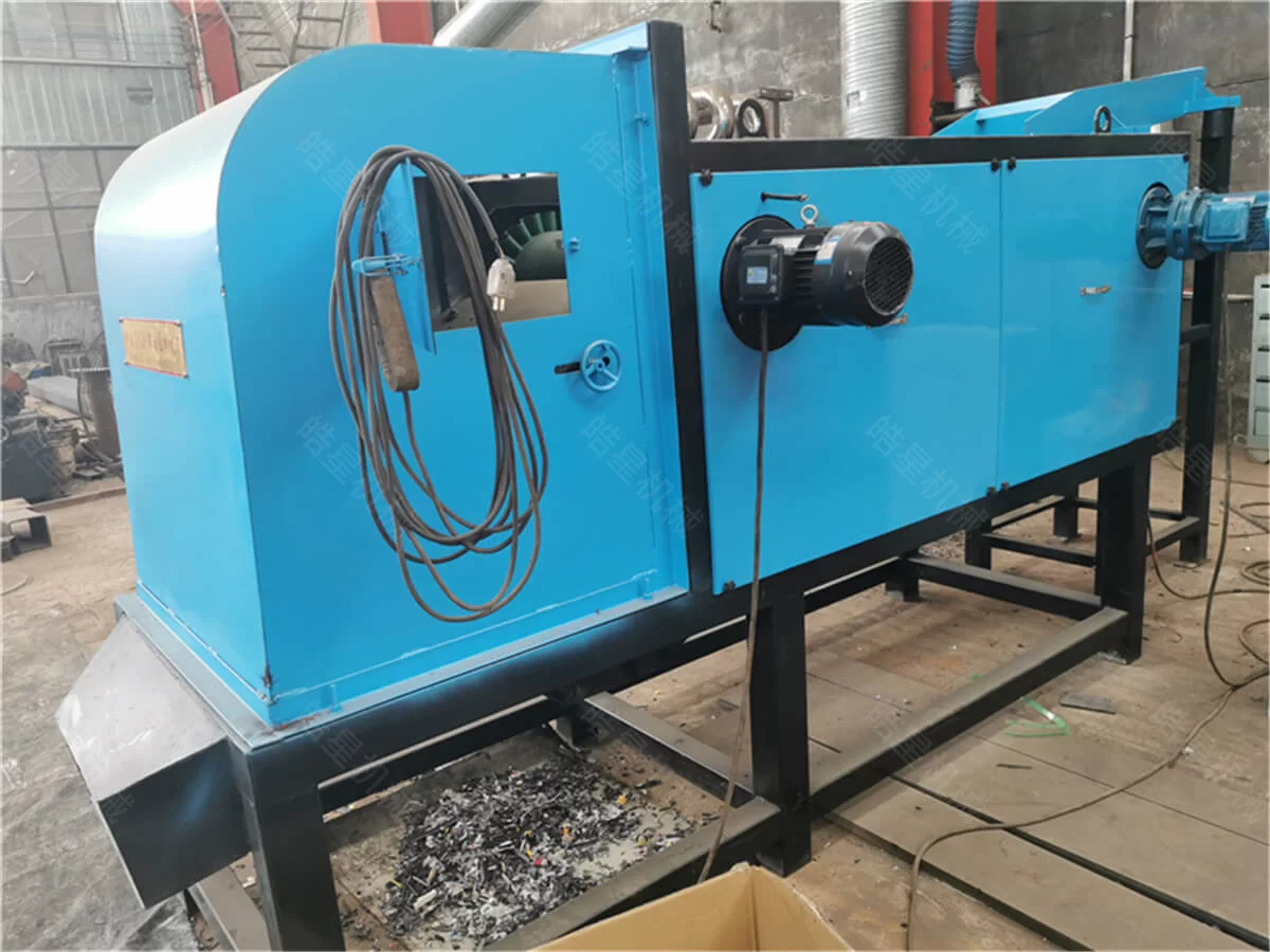
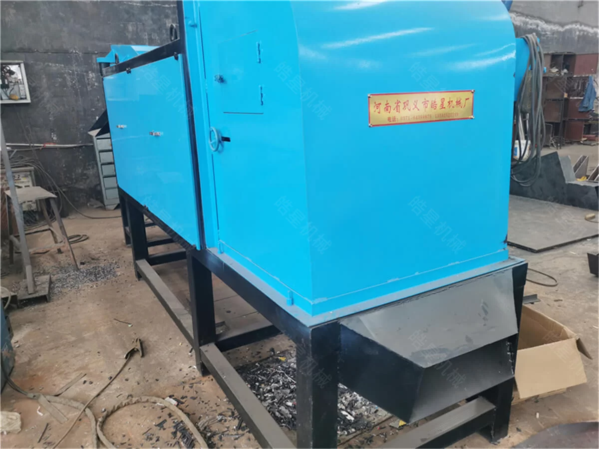
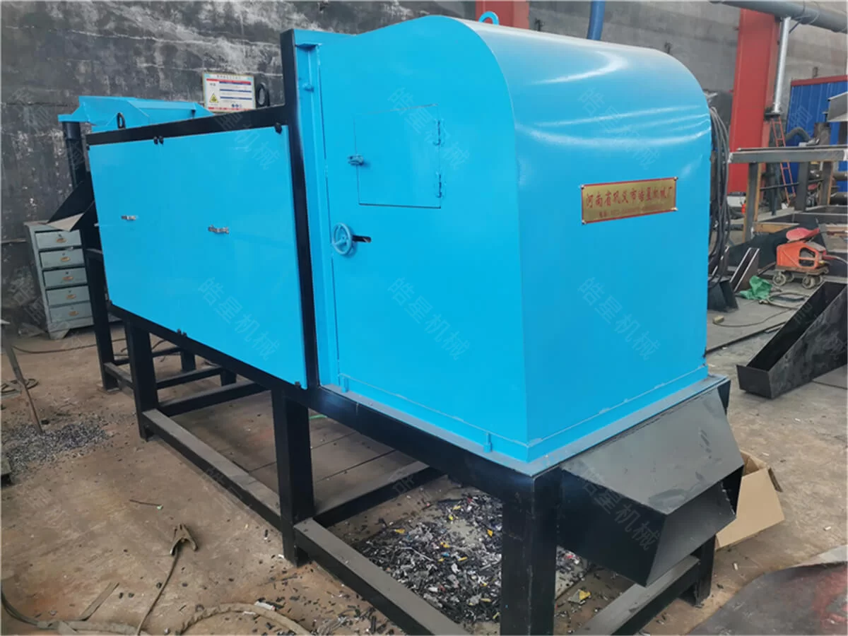
Factory photos of more than ten 1200 eddy current separators in the workshop stock area, showing completed machines undergoing configuration checks and delivery preparation.
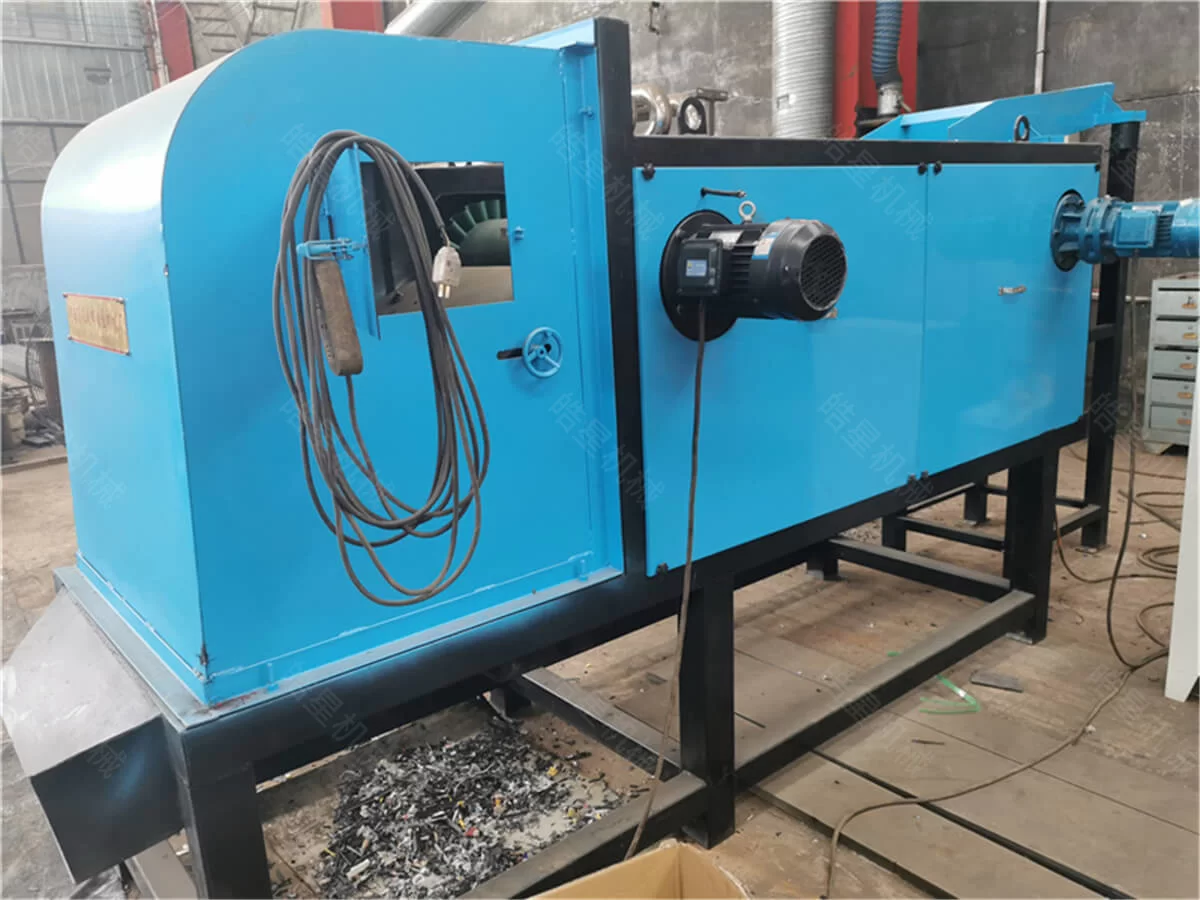
More than ten 1200 eddy current separators are currently arranged in the factory stock area after completing their main manufacturing and assembly work. The workshop photos show the actual equipment condition before final configuration checks, packing and delivery preparation.
The machines share a nominal sorting width of 1200 mm, but they should not be treated as one identical batch for a single project. Individual units may have different electrical standards, conveyor dimensions, discharge heights, protective structures and control requirements.
Before packing, workshop personnel check each machine against its corresponding equipment list. This helps ensure that the separator body, drive system, belt, rotor section, divider and electrical components match the intended project configuration.
More Than Ten 1200 Models in the Stock Area
The concentrated stock area provides a direct view of the factory’s current production status. More than ten completed or nearly completed machines are positioned together, allowing the main structures and conveyor sections to be inspected before individual packing begins.
The stock-area inspection covers:
Equipment model and working width
Machine frame condition
Sorting belt installation
Rotor assembly
Belt and rotor drive systems
Protective cover installation
Material divider configuration
Feeding and discharge direction
Electrical control components
Matching accessories
Equipment identification
External machine condition
Although the machines have a similar appearance, project-specific details must be checked separately. A unit prepared for one recycling line may require a different inlet height, outlet arrangement or electrical standard from another 1200 model.
What the 1200 Model Means
The 1200 designation refers to the nominal sorting width of the machine. This width provides a working area across which prepared material can be distributed before passing through the separation zone.
A wider sorting belt can accommodate a broader material layer, but working width alone does not determine hourly capacity. Actual processing performance also depends on:
Material composition
Particle size
Bulk density
Feeding thickness
Moisture
Contamination
Belt speed
Material distribution
Upstream screening
Required separation result
If the incoming material is concentrated on one side or enters in a thick overlapping layer, the full working width cannot be used effectively. For this reason, the feeding section must be selected and adjusted together with the separator.
Main Components of the 1200 Eddy Current Separator
The machines shown in the workshop stock area consist of several connected working sections.
Machine frame
The frame supports the sorting belt, rotor assembly, drive components and discharge section. Frame condition and alignment are inspected before continuous trial operation.
Sorting conveyor belt
The belt carries prepared material toward the discharge end. Correct tension and stable tracking are important because the position at which particles leave the belt affects their discharge trajectories.
High-speed magnetic rotor
The magnetic rotor operates beneath the belt near the discharge end. During operation, the rotor produces the rapidly changing magnetic field required for non-ferrous metal separation.
The rotor does not pull aluminum through the belt. Instead, the changing field induces electrical currents in conductive metal and changes its movement as the material leaves the conveyor.
Independent drive system
The sorting belt and magnetic rotor perform different functions and therefore use separate drive arrangements. Their operating directions and mechanical conditions are checked during workshop testing.
Adjustable material divider
The divider is installed between the expected discharge paths of conductive and non-conductive materials. Its final position must be adjusted according to the customer’s actual processed material after installation.
Protective covers
Protective structures enclose the rotor, transmission and other moving sections according to the equipment design. Their installation is checked before packing.
Electrical control system
The control system manages the separator and coordinates its operation with the associated feeding and discharge equipment. Voltage, frequency and control requirements must be verified for each project.
Working Principle
An eddy current separator is used to recover suitable conductive non-ferrous metals from non-conductive materials.
Before sorting, the incoming scrap should be crushed or otherwise reduced to an appropriate size. Exposed iron and steel should normally be removed before the material reaches the eddy current section.
When aluminum or another suitable conductive metal enters the changing magnetic field near the rotor, electrical currents are induced inside the metal. The resulting force changes the particle’s discharge trajectory.
Conductive metal is projected farther from the normal belt path, while plastic, rubber, glass and other non-conductive materials follow a different route. The adjustable divider directs the separated fractions into different outlets.
The process depends on individual particles being sufficiently released. If aluminum remains firmly connected to plastic or steel, the combined piece may not follow the expected trajectory.
Why Material Preparation Is Necessary
The separator is a sorting machine. It does not replace a crusher, shredder or screening system.
Complete aluminum profiles, window frames, dense scrap bales and large composite components should not be placed directly onto the sorting belt. These materials must first be prepared according to their size and structure.
A typical preparation sequence can include:
Incoming material inspection
Removal of unsuitable objects
Coarse size reduction when necessary
Main crushing
Particle-size screening
Ferrous metal removal
Controlled material distribution
Eddy current separation
Separate collection of the output fractions
A magnetic separator can be arranged before the eddy current stage to recover exposed iron and steel. Removing ferrous material first gives the downstream separator a more suitable feed and reduces the amount of unwanted iron entering the non-ferrous output.
Typical Materials for the 1200 Model
With suitable upstream preparation, the 1200 model may be used for material streams containing:
Crushed aluminum profiles
Processed thermal-break aluminum
Aluminum and plastic mixtures
Crushed aluminum door and window profiles
Aluminum casting fragments
Conductive metal recovered from dismantling
Processed appliance components
Mixed non-ferrous metal fragments
Aluminum mixed with rubber or plastic residue
Suitable conductive particles in mixed recycling material
The name of the material alone is not enough for equipment selection. Particle size, shape, moisture, conductivity and the amount of non-metallic residue all affect the sorting result.
Flat aluminum pieces may behave differently from irregular casting fragments. Thin particles may also follow different trajectories from heavier pieces, even when both are aluminum.
Factory Inspection Before Packing
The equipment shown in the photos has completed the primary assembly stage. Before the machines move from the stock area to packing, the main mechanical and electrical sections are inspected.
Rotor Operation
The rotor is operated to check:
Rotation direction
Mechanical stability
Abnormal operating noise
Unusual vibration
Drive connection
Protective cover clearance
An empty-load rotor test confirms the mechanical condition of the assembly. It should not be presented as proof of a specific separation rate because the final sorting result depends on the customer’s actual material.
Belt Tracking
The sorting belt is checked during continuous operation. It should remain properly aligned rather than moving toward one side of the conveyor.
Workshop personnel inspect:
Belt tension
Tracking position
Surface condition
Connection points
Clearance around the rotor section
Drive direction
Discharge position
Incorrect belt tracking can cause uneven wear and change where the material leaves the discharge end.
Drive System
The belt motor, rotor motor and related transmission parts are checked for correct operation. Fasteners around the drive system are inspected again after trial running.
Because the rotor and belt operate at different speeds, the two systems must be tested according to their respective functions.
Divider and Discharge Section
The divider is checked for installation and adjustment range. The stock-area position is only a preliminary setting.
After the machine reaches the customer’s production site, the final divider position should be determined by observing the actual trajectories of the metal and non-metallic fractions.
The discharge section should provide sufficient clearance for:
Conductive metal output
Non-conductive residue
Collection containers
Downstream conveyors
Adjustment and maintenance access
Electrical Functions
The basic electrical inspection can include:
Start and stop controls
Emergency stop response
Motor rotation direction
Control cabinet condition
Cable routing
Terminal connections
Project voltage
Electrical frequency
Coordination with feeding equipment
When the separator is integrated into a complete system, the control sequence should reduce the risk of material accumulating between connected machines.
Feeding and Material Distribution
Stable feeding has a direct effect on separator performance.
The prepared material should enter the belt in a controlled layer rather than in large piles. Excessive overlap can prevent some metal particles from responding consistently near the rotor.
A suitable feeding arrangement should provide:
Continuous material movement
Distribution across the working width
Limited particle overlap
Stable feed thickness
An adjustable feeding rate
Sufficient spacing between particles
The upstream conveyor and feeding equipment should be matched to the separator’s effective working width. A conveyor described as 1200 mm wide does not automatically provide an even 1200 mm material layer.
Sidewall position, discharge shape and actual material distribution also need to be considered.
Relationship with a Complete Sorting Line
The 1200 separator can operate as a downstream unit in a non ferrous metal sorting line.
Depending on the incoming scrap, a complete system may include:
Feeding conveyor
Shredder or crusher
Discharge conveyor
Screening equipment
Magnetic separator
Material distribution equipment
Eddy current sorting section
Conductive metal outlet
Non-metallic residue outlet
Electrical control system
Not every project requires all these machines.
Clean and screened particles may only require controlled feeding and sorting. Composite aluminum scrap may require crushing, screening and iron removal before it is suitable for eddy current separation.
The separator should therefore be selected as part of the complete material flow rather than as an isolated machine expected to correct every upstream processing problem.
Factors Affecting Separation Performance
The actual sorting result depends on the condition of the material and the operating settings.
Particle size
A controlled particle-size range generally produces more stable discharge trajectories than a mixture containing both oversized pieces and fine particles.
Material liberation
Metal and non-metallic components should be physically released. A separator cannot divide materials that remain firmly connected.
Feeding thickness
A thick material layer increases particle overlap and can reduce sorting consistency.
Belt speed
The belt speed affects the point and distance at which particles leave the machine.
Rotor operation
Stable rotor operation is required to maintain the changing magnetic field used for separation.
Divider position
The divider must be set between the actual discharge paths of the output materials.
Moisture and contamination
Wet, oily or dirty particles may stick together and become more difficult to distribute evenly.
Material shape
Flat, round, irregular and wire-shaped pieces may follow different paths even when they are made from the same metal.
Same Model, Different Project Configurations
The more than ten machines visible in the stock area use the same basic model designation, but they may not have completely identical configurations.
Possible project differences include:
Electrical voltage
Electrical frequency
Motor specification
Conveyor length
Inlet height
Discharge height
Divider structure
Protective cover design
Control cabinet configuration
Cable standard
Plug and connector requirements
Matching accessories
Downstream conveyor arrangement
Each machine is therefore checked using its individual configuration list before packing.
The stock-area photographs record a real production stage, but they should not be interpreted as showing one customer’s complete order unless that information has been specifically confirmed.
Information Required Before Selecting a 1200 Model
Customers considering a 1200 separator should provide:
Photos or videos of the incoming material
Material composition
Maximum and average particle size
Percentage of conductive metal
Types of non-metallic residue
Amount of ferrous contamination
Material moisture
Bulk density
Required hourly capacity
Upstream crushing equipment
Existing screening equipment
Conveyor working width
Available installation area
Required discharge arrangement
Local voltage and frequency
Expected output fractions
Representative material information is more useful than a general description such as “mixed metal” or “aluminum scrap.” Materials with similar names may behave differently because of differences in particle size, shape and contamination.
More Than Ten Machines Awaiting Final Preparation
The workshop photos show more than ten 1200 eddy current separators arranged in the factory stock area. Their main mechanical structures have been completed, while final inspection, configuration confirmation and delivery preparation are being organized according to the corresponding project lists.
The concentrated view of multiple machines documents the current workshop production stage. It allows the frames, sorting belts, rotor sections, drive systems and discharge structures to be seen before the units are individually protected and packed.
The next step for each machine depends on its project configuration. Accessories, electrical requirements and delivery components are verified before the equipment leaves the stock area.