Metal Turnings Shredder Working Process
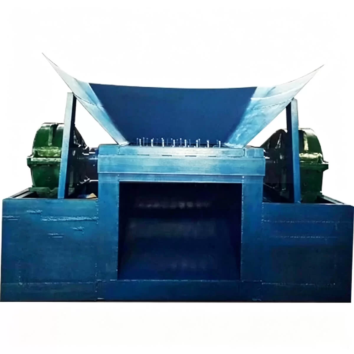
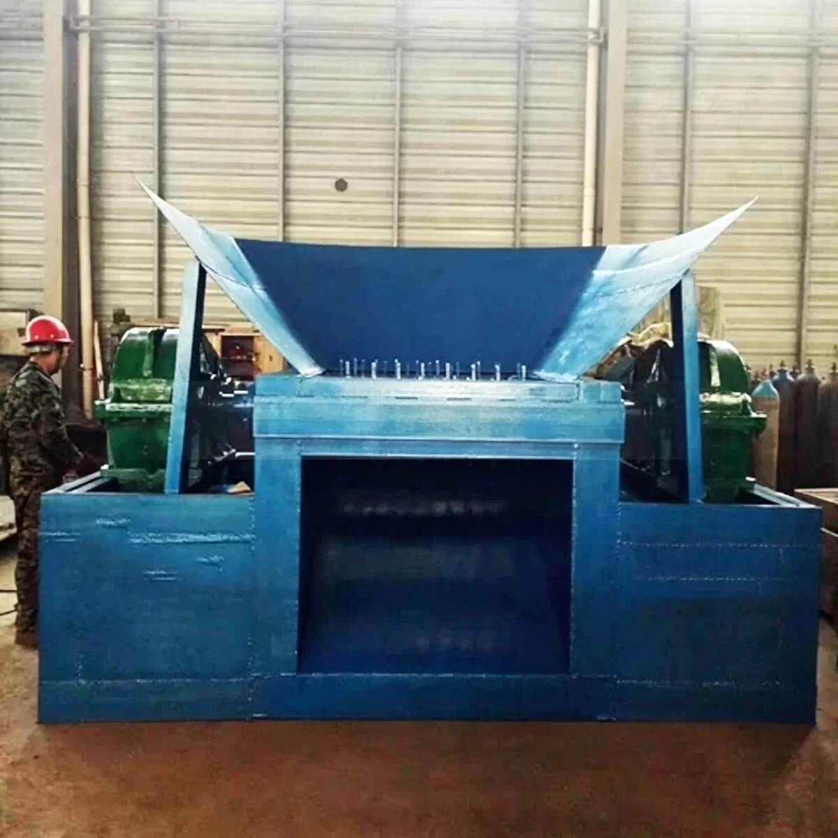
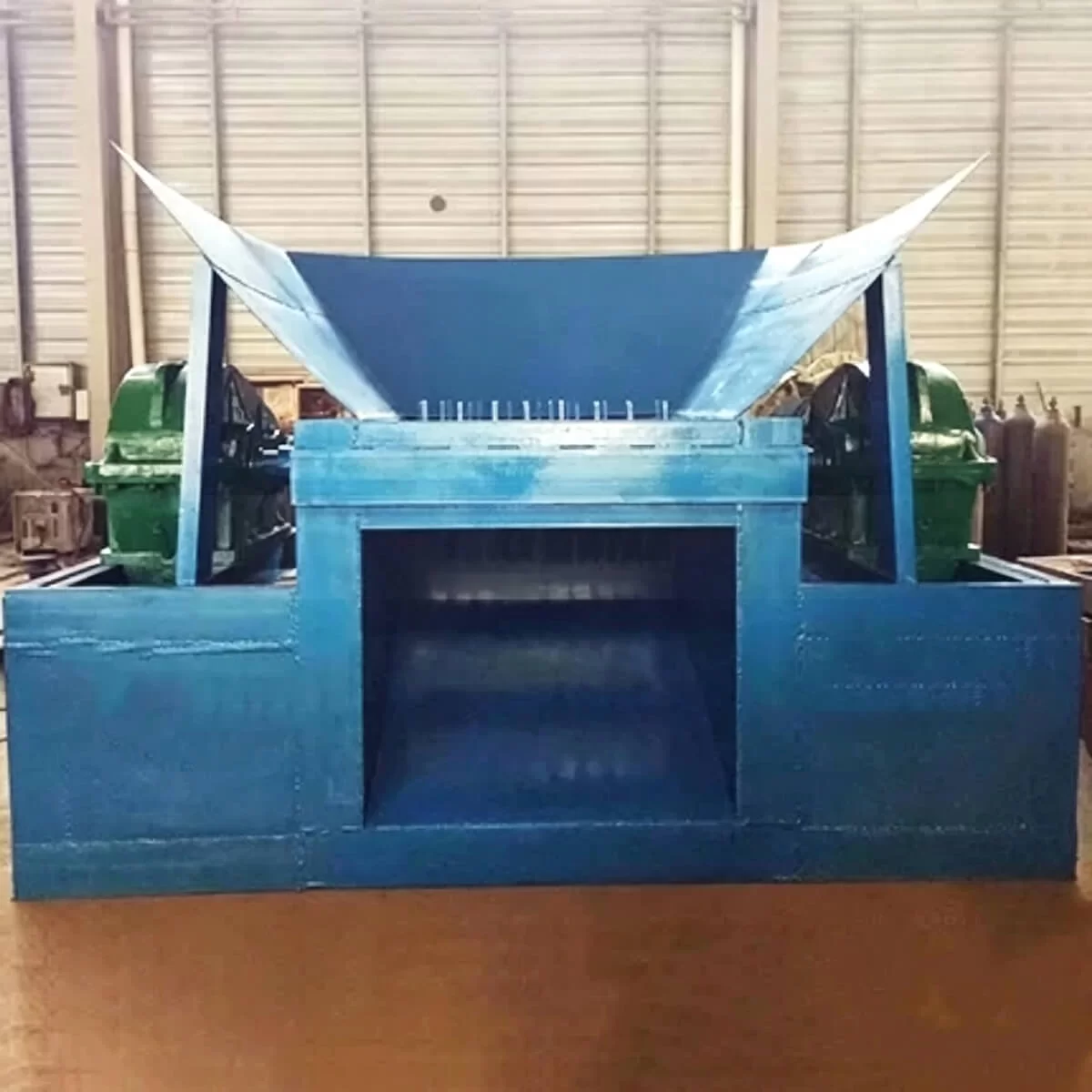
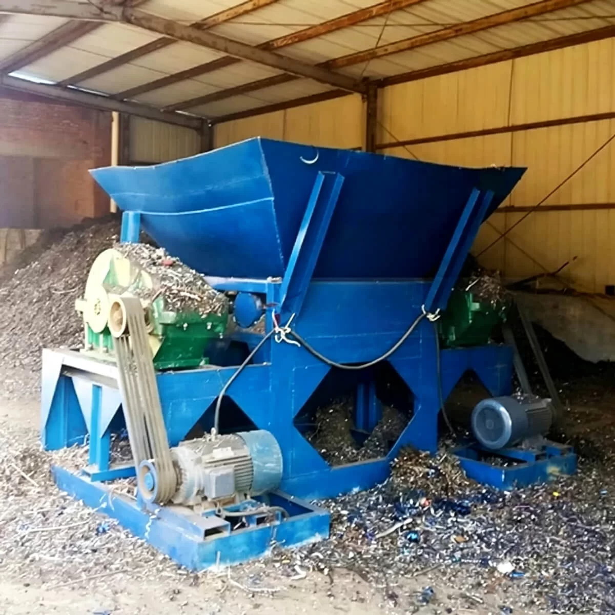
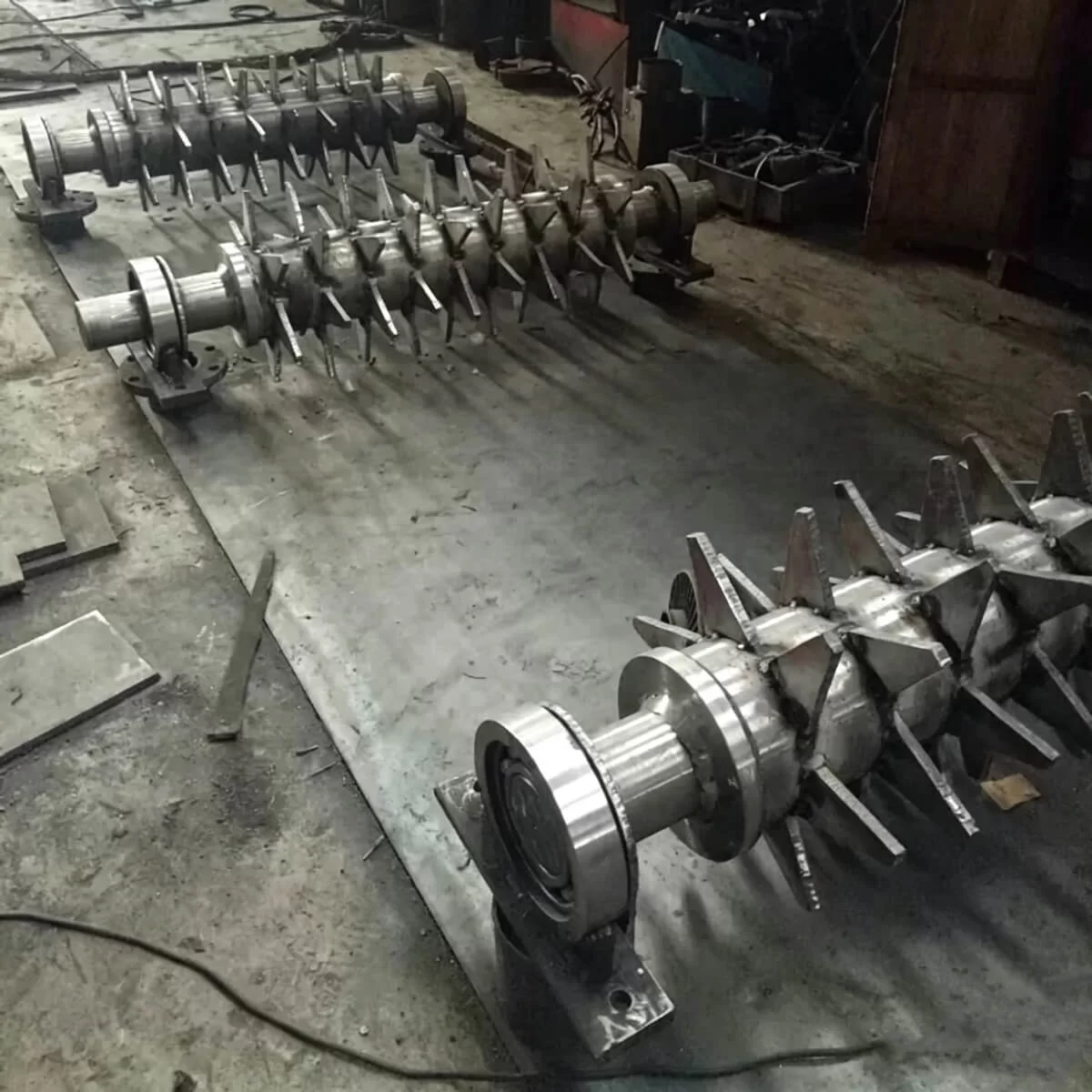
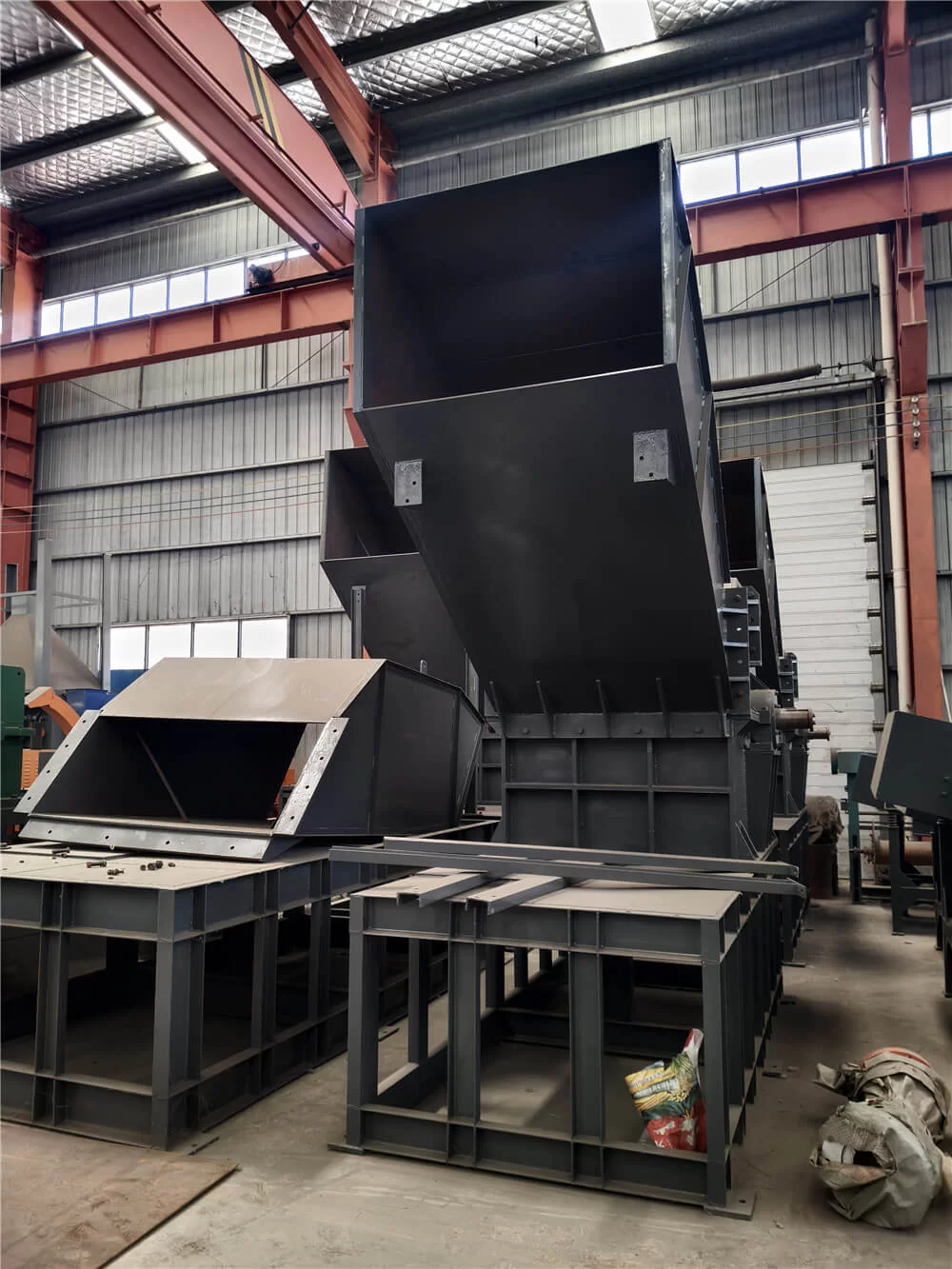
The metal turnings shredder, also called an iron chips crusher, uses a twin shaft shearing and tearing structure. The main components include a feeding hopper, two cutter shafts, toothed alloy cutter discs, heavy-duty gear reducers, drive motors, reinforced frame, electric control system and discharge equipment.
Material Inspection and Feeding
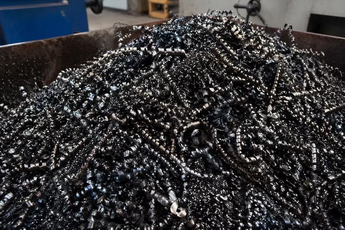
Loose, curled or tangled metal turnings are loaded into the feeding hopper and guided toward the shredding chamber. The feeding method should be selected according to the chip length, bulk density, tangled condition and required processing capacity.
Before feeding, the material should be checked for thick solid metal parts, tools, sealed objects and other unsuitable foreign material. Hot chips, metal powder, grinding dust, flammable cutting fluids and materials of unknown composition require separate evaluation.
Twin Shaft Shearing
Heavy-duty gear reducers drive two parallel cutter shafts to rotate toward each other at low speed and high torque. The toothed alloy cutter discs grip and pull tangled metal turnings into the shredding chamber, where the material is repeatedly squeezed, sheared and torn into shorter, looser and more manageable pieces.
This working method is suitable for long, curled and tangled steel turnings, iron swarf and selected machining chips that are difficult to convey, store or feed directly into downstream equipment.
Coarse Size Reduction
Unlike a high-speed hammer crusher, the machine does not mainly rely on impact force or a screen to produce a precise final particle size. The processed output remains irregular, and its condition depends on cutter width, tooth design, cutter spacing, shaft speed, chip thickness and the number of cutting passes.
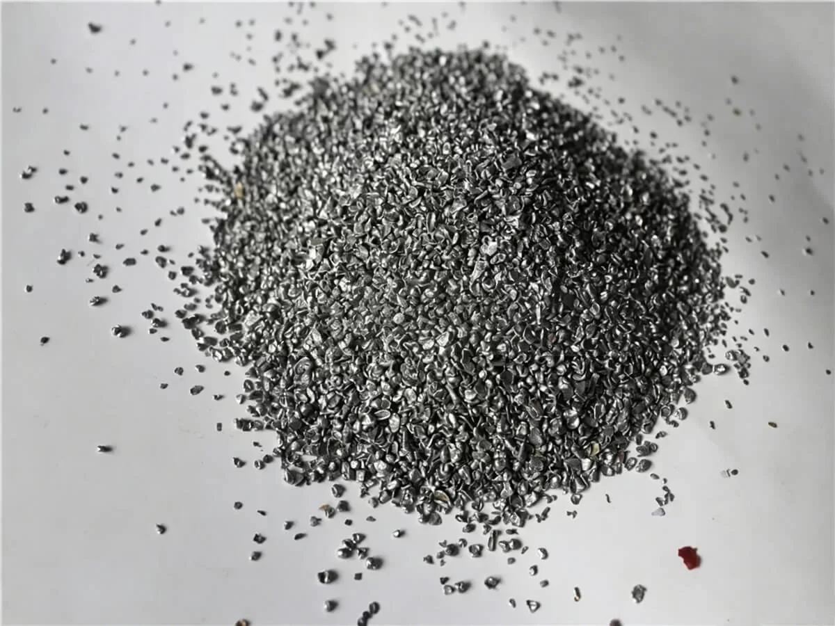
After processing, long and tangled turnings become easier to convey, collect, store, transport, screen, briquette or prepare for further recycling.
Material Discharge
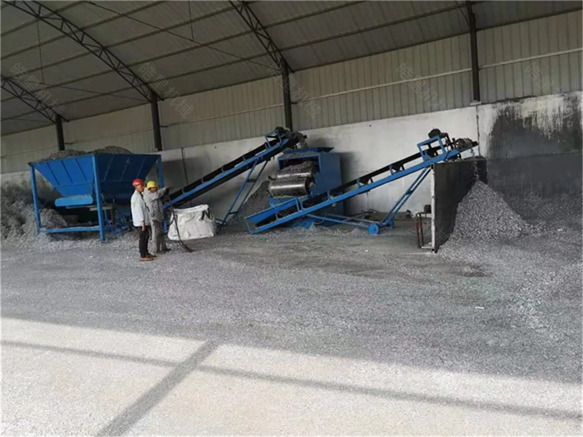
The processed metal turnings are discharged by conveyor or collected below the machine outlet. Discharge equipment can be selected according to the plant layout, material condition and downstream process.
Short, loose chips and brittle cast iron borings may not require shredding. Representative material photos, videos or samples should be evaluated before the equipment configuration is confirmed.
Optional Liquid Collection and Dust Control
When the incoming turnings contain residual cutting fluid, a liquid collection tray or downstream fluid separation system can be considered according to the material condition. The shredder itself does not guarantee complete oil or coolant removal.
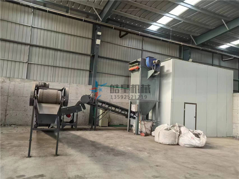
Dust collection or light-material separation equipment may be added when the processed material contains dust, fines or lightweight non-metallic impurities. The suitability of this equipment depends on the actual material composition and should not be treated as a standard configuration for every project.
Optional Magnetic Separation
A magnetic separator may be added when ferrous metal needs to be recovered from suitable mixed processed material. For clean, single-metal iron or steel turnings, magnetic separation may not be necessary.
Magnetic separation does not separate different grades of magnetic steel and does not remove cutting oil from the processed material.
Automatic Reverse Protection
When excessive resistance or a material jam is detected, the control system can stop and reverse the cutter shafts to help release the obstruction. This function helps reduce prolonged overload on the cutter discs, shafts, gear reducers and motors.
Automatic reverse protection does not replace material inspection. Thick solid metal parts and unsuitable foreign objects should be removed before feeding.